
Written by php editor Banana, this article will introduce you to the specific steps of modeling torsional bending moment in Solidworks. Solidworks is a powerful three-dimensional modeling software. Mastering modeling skills is crucial for engineering designers. By studying this article, you will understand how to accurately implement the torsional bending moment modeling process in Solidworks, helping you improve your modeling capabilities and efficiency.
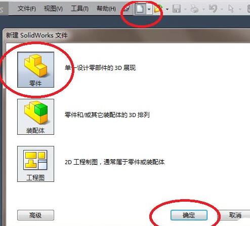
1. As shown in the red box selection in the figure, open Solidworks and create a new part file.
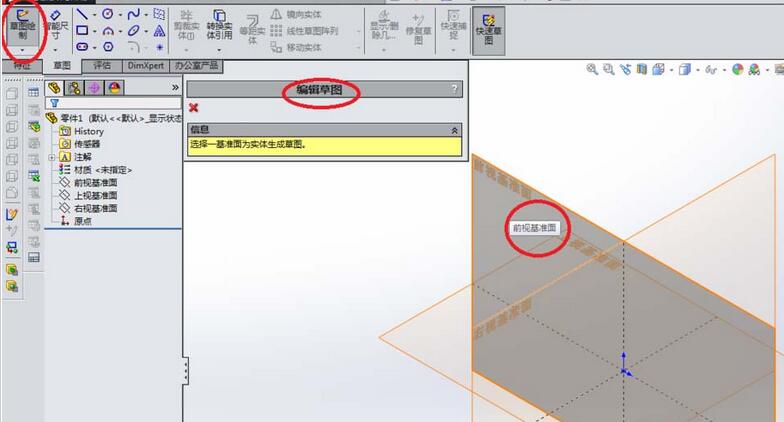
2. Enter the 3D mode of the software and create a sketch. as the picture shows.
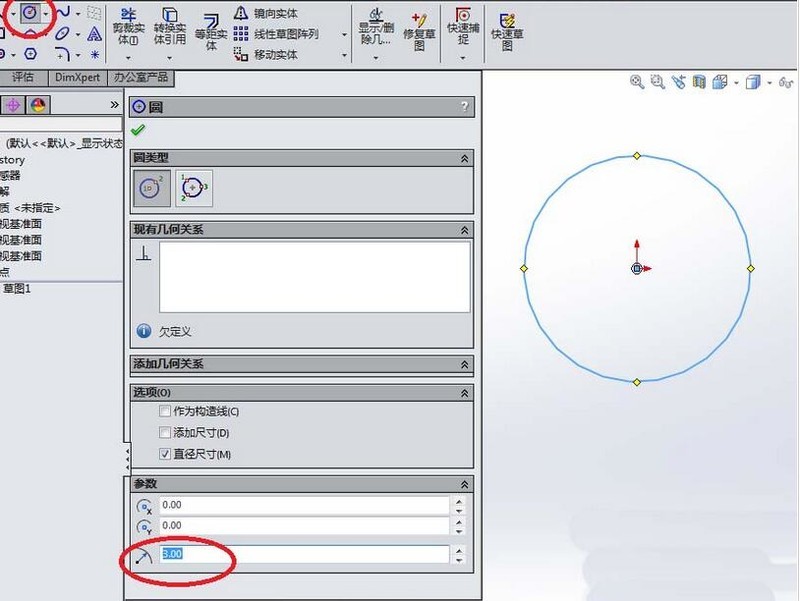
3. After entering the sketch plane, first draw a circle. The center of the circle should preferably coincide with the origin of the coordinates. As shown in the picture, the radius of the circle I drew is 3 (diameter is 6). After drawing this circle, exit the sketch.
4. Create a spiral. Note, as shown in the picture, you can choose the appropriate pitch of 0.4 and number of turns of 10. The most important thing is the starting angle selected in the red box. This is best 0, otherwise it will be a little troublesome later.
5. The spiral was created in the previous step. In this step, continue to create a sketch, but this time the upper visual datum plane is used as the sketch plane.
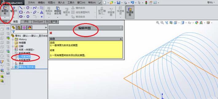
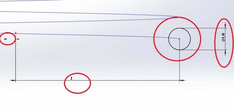
6. As shown in the picture, enter the sketch state and draw a circle with a diameter of 0.4. Pay attention to the positioning size. The center of the circle must coincide with the starting point of the spiral, otherwise you will not know what the diameter of the scanned entity is.
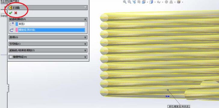
7. As shown in the figure, activate the [Scan] command, select a circle of 0.4 for the outline, and select the spiral for the path. The order of selection does not matter, as long as you do not select the path as a circle and the outline. It becomes a spiral. After completing this scanning operation, the main part of the torsion spring is completed.
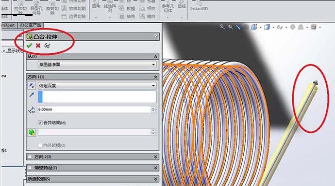
8. As shown in the figure, continue to use sketch 2 (that is, a circle with a diameter of 0.4) to perform the stretching operation. Click the [Extrude Boss/Base] command in the toolbar, select Sketch 2, and set the extrusion height to 6.0. I think this number is better. After the stretching is completed, a section of the torsion spring is completed.
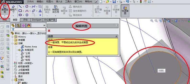
9. As shown in the figure, continue to create a sketch. This time the plane on which the sketch is created is no longer the datum plane in the coordinate system, but the plane at the other end of the scanned entity. It is the dark plane shown in the red box in the figure.
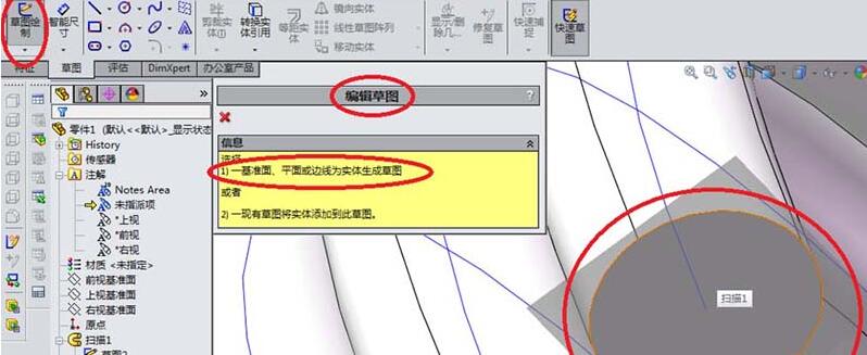
10. As shown in the picture, continue to draw a circle. The circle must coincide with the scanned section, so the size must be 0.4 in diameter (radius 0.2 - no way, SolidWorks generally displays the radius). After you finish drawing the circle, remember to exit the sketch.
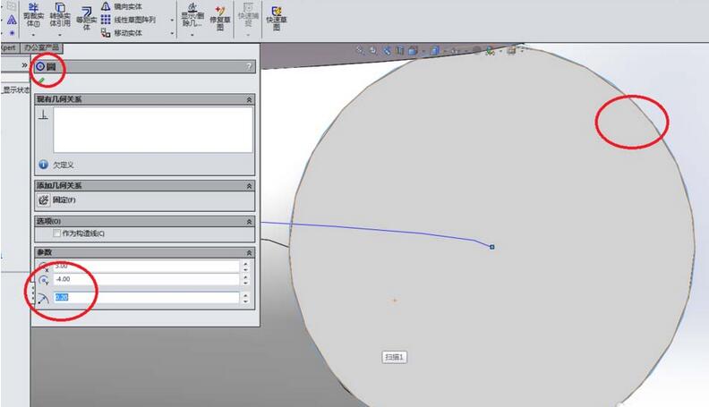
11. As shown in the figure, return to the feature toolbar and click [Extrude Boss/Base]. The same operation and the same data are performed, except that the sketch is replaced by the 0.4 just drawn. sketch of the circle. See the stretching effect in the picture below.
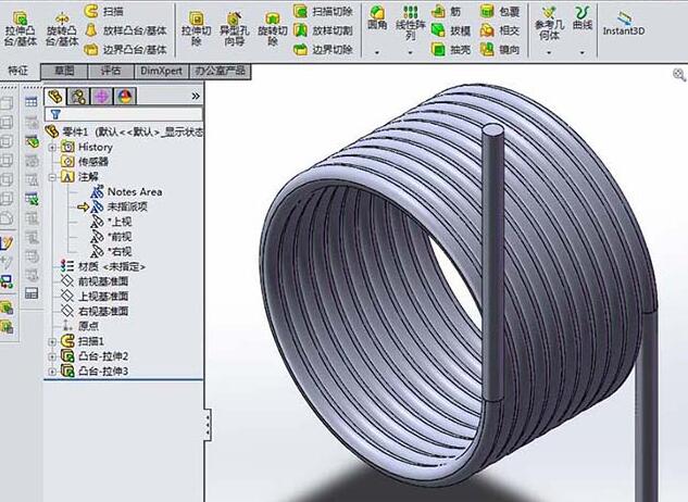
12. At this point, the torsion spring has been created successfully, as shown in the picture, this is the rendering effect.
The above is the detailed content of Describe the specific steps for modeling torsion springs in Solidworks. For more information, please follow other related articles on the PHP Chinese website!


