
In Revit modeling, setting walls constructed of multi-layer materials is a common requirement. For beginners, this process can be confusing. PHP editor Youzi will introduce the steps of building a multi-layer wall in detail and guide you to complete the task step by step. Read on to learn how to easily create complex wall structures and enhance the accuracy and efficiency of your Revit modeling.
In the past expression habits of the AutoCAD platform, walls are generally expressed with double lines. For example, [200mm thick masonry wall] is expressed with double lines with a spacing of 200mm. As for the filling layers and surface layers on both sides of the masonry, they are generally described in the general description or construction list and are not shown on the plan view. They are only shown on the local enlarged plane or large sample with a scale of less than 1:50. The schematic diagram of the multi-layer structure of the wall is shown in the figure.
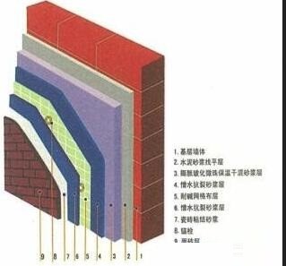
However, on the Revit platform, the wall settings are more complicated. The material can be set to a multi-level composite material, as shown in the figure, or only a single layer of material can be set. The material settings It affects both the plane expression of the wall and the view expression of the vertical section. It also affects the collaborative design between professionals, subsequent project quantity statistics, 4D simulation, etc. Therefore, the setting of the wall material needs to be comprehensively considered.
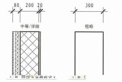
Starting from the concept of BIM, the BIM model should faithfully reflect the material and structure of the object (especially the construction drawing stage). However, if the wall materials are completely set according to the wall structure level, it will brings many problems.
(1) Problems with drawing expression: Revit can set the detail level of the view to [Coarse], and the wall is displayed as a double line, but the distance between the double lines is the total thickness of the wall, which does not comply with [double line]. The line only represents the thickness of the core layer], as shown in the figure:
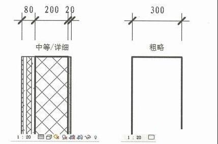
(2) When working with upstream and downstream software models, information may be lost or missed early, such as through When you import the Revit model into Tekla Structure in Tsuji IFC format, you will find that the walls are displayed according to thickness, and it is easy to cause errors if you do not design based on Tsuji's model.
(3) In reality, the construction of the core layer of the wall is separated from the construction of the filling layer and facing layer. However, when the Revit model is imported into Navisworks for 4D construction simulation, it is difficult to combine these integrated components. The two construction processes are expressed separately.
If we follow the previous simplified approach and only consider the core layer of the wall, in addition to the shortcomings of failing to fully express the wall structure, there are also problems with graphic expression, which mainly affects the expression of the vertical section. The edge lines of structural components such as beams, plates, and columns will be exposed, which will bring a lot of line processing work, as shown in the figure:
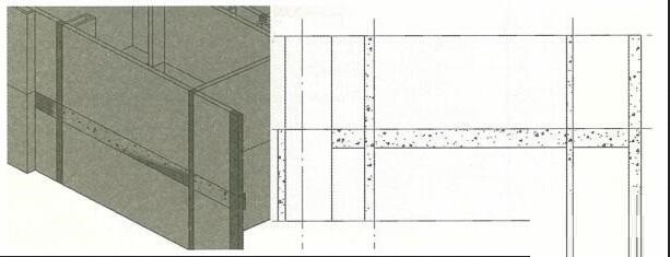
In order to solve these problems, we recommend that the wall press Set the material according to this principle: set the core layer separately as - road wall, and set the filling layer and surface layer on both sides as - ~ road wall (referred to as "facing layer"). In actual projects, the facing layer of the interior wall is often ignored, and only an additional facing layer wall is provided on the outside of the exterior wall, as shown in the figure:
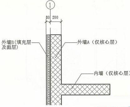
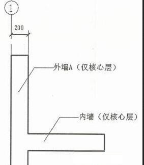
For 1: For large floor plans with a scale of 100 or greater, there is no need to express the filling layer and surface layer. Therefore, in the visibility settings of the view, the facing layer walls need to be filtered out through the filter and set to not be displayed. The conditions of this filter can be determined by yourself. For example, set according to the condition of [the type name of the wall contains 'finishing layer'], as shown in the figure, set it to not display, and set the detail level of the wall to After [Rough], the effect is as shown in the figure, which conforms to the plane expression of the traditional wall.
In the elevation view, open the facing layer wall and use this layer of wall to block the edges of the beams, slabs and columns. The effect is as shown in the figure.
Although this is a bit troublesome during modeling, it basically solves the problem of graphic expression. It also solves the problem of separating the core layer and the decorative layer of the wall during subsequent applications such as 4D simulation. When exporting to downstream majors, you need to pay attention to the needs of the downstream majors. For example, when exporting to structural calculation software, there is no need to export the facing layer wall.
In addition, for exterior walls that are modeled as separate two-layer walls, when inserting doors and windows, you only need to insert them in the core layer wall, and then use the [Connect] command to connect the two-layer walls. The door and window openings are synchronized on the outer facing wall, as shown in the picture.
The above is the detailed content of Detailed steps for setting up walls constructed of multi-layer materials in Revit. For more information, please follow other related articles on the PHP Chinese website!


