
php editor Xiaoxin introduces to you the steps to make a set of 90-degree elbows in the Revit pipe fitting family. Revit is a BIM software widely used in the fields of architectural, structural and mechanical and electrical engineering. The piping system is one of the common systems in construction projects, and how to mass-produce elbows in the piping system is an important operating skill in Revit software. This article will introduce in detail the production process of 90-degree elbow in Revit pipe fitting family. I hope it will be helpful to everyone.
1. Select the family template and set the family parameters and family type.
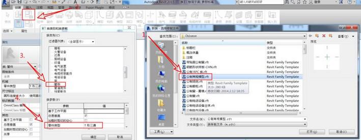
Open Revit, click New Family, select the [Metric Conventional Model] family template to create a family, click the [Family Category and Family Parameters] button as shown below, select the family category as [Pipefit], and set the family parameters under the list The part category is [Elbow]; other parameters can be set according to actual needs.
2. Create the main body model of the elbow by lofting it out.
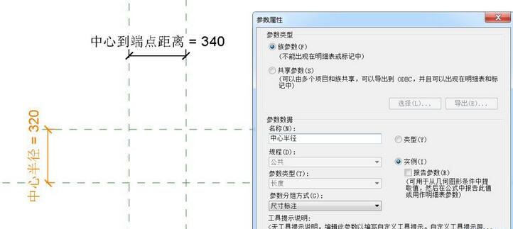
As shown in the figure, draw a horizontal and vertical reference plane, use the Alignment Dimension command under the Annotation tab to mark the distance to the default reference plane, and add instance parameter labels, named [center to end point distance], [Center Radius].
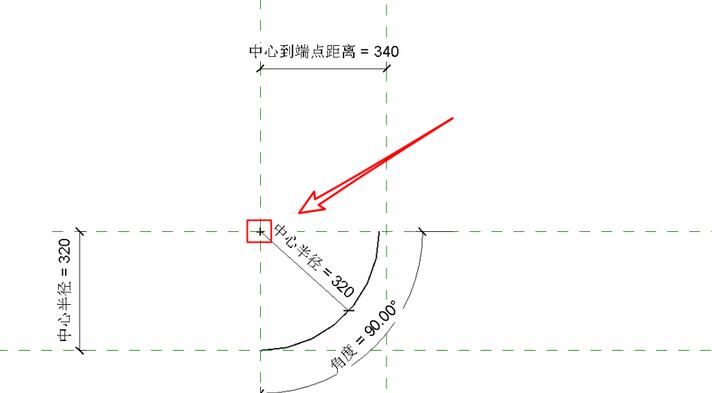
Click the [Model Line] tool under the Create tab, use the [Center-End Point Arc] command, take the intersection of the horizontal and vertical reference planes just drawn as the center of the circle, and draw four points Create a circle, as shown in the figure, and add an angle label to mark the angle of the model line (click the model line directly to change the angle temporary dimension to a permanent dimension), then specify its radius as the [Center Radius] label, and finally Click the model line, check [Center Mark Visible] in the instance attribute bar, and lock the center mark alignment at the intersection of the previously drawn horizontal and vertical reference planes.
Click the loft tool under the Create tab, pick the model line as the loft path, and click Finish; then edit the circular outline in the three-dimensional view and add the instance parameter label [Pipe Outer Radius] 】Mark the circle radius value and click Finish.
3. Import the search table data and associate the model parameters.
Open the [Family Type] dialog box and add a parameter named [Lookup Table] text type.
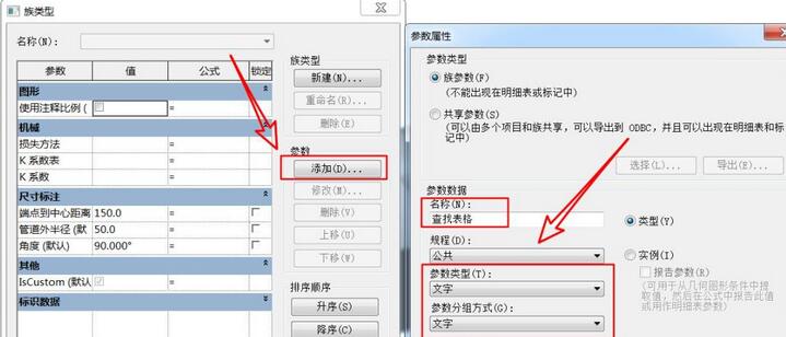
Then click the [Manage] button under [Lookup Table] in the [Family Type] dialog box. The import file path is: [Elbow - Generic] under C:ProgramDataAutodeskRVT 2015Lookup TablesPipe ( Example) Table document; at the same time, copy and paste the name of the table document as the [Lookup Table] value.
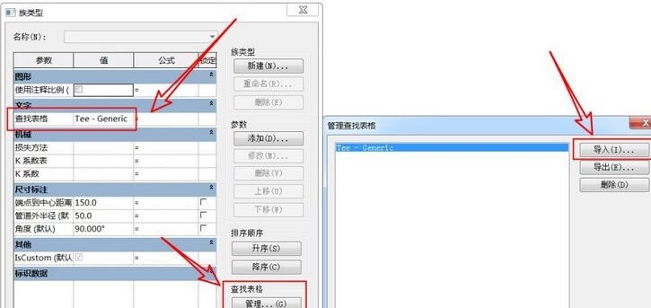
According to the imported table content, we also need to add instance parameters in the family type dialog box: pipe outer diameter, nominal diameter, center to endpoint; and add formula associated parameter values: pipe outer diameter Radius = pipe outer diameter / 2, pipe outer diameter = size_lookup (lookup table, "FOD", nominal diameter 10.4 mm, nominal diameter), endpoint to center = size_lookup (lookup table, "CtE", 1.02 * nominal diameter - 1.5 mm , nominal diameter).
4. Check and correct, and complete the final model.
When the nominal diameter is too large and exceeds the center radius value, the model cannot be created at this time, and we need to correct this situation.
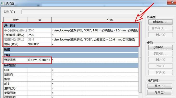
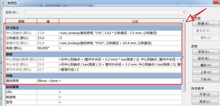
Enter the formula: center radius = if (center to end point / tan (angle / 2) > outer radius of pipe fitting 3.2 mm, center to end point / tan (angle / 2), pipe fitting Outer radius 3.2 mm); In addition, the distance from the center to the endpoint should be equal to the center radius value, and it is necessary to ensure that the horizontal distance between the model and the center reference changes flexibly. The distance value from the center to the endpoint also needs to be corrected to determine how to obtain the value. Here we add Such a formula: distance from center to end point = if (center to end point> (outer radius of pipe fitting 3.2 mm) * tan (angle/2), center to end point, (outer radius of pipe fitting 3.2 mm) * tan (angle/ 2)) ;The model is basically created.
5. Add connectors and import the project.
Click [Pipe Connectors] under the [Create] tab to add connectors to the elbows respectively, and associate the diameter value of the connector to the nominal diameter label.
The above is the detailed content of Steps to create 90-degree elbow in Revit pipe fitting family. For more information, please follow other related articles on the PHP Chinese website!
 c language else if statement usage
 The difference between server and cloud host
 What plug-ins are needed for vscode to run HTML?
 How to delete blank pages in word
 Usage of #include in C language
 linux view network card
 How to solve the problem of dns server not responding
 How to read files and convert them into strings in java


