php editor Apple introduces you to the programming and operation methods of Mitsubishi PLC programming software (GX Developer). GX Developer is a professional PLC programming software launched by Mitsubishi Electric, which can be used for program writing and debugging of Mitsubishi PLC. Through GX Developer, users can perform operations such as logic program writing, parameter setting, and online monitoring. This article will introduce in detail how to program and run PLC programs in GX Developer to help you better master Mitsubishi PLC programming skills.
1. Programming operation
In the preparation work before programming, it is necessary to ensure that the PLC and the computer are connected correctly, and the correct cable and converter are used to connect the computer's RS232C port and the PLC. Before starting programming, you must ensure that the PLC is in the "stop" state and the computer and PLC are powered on at the same time. Proper execution of these steps is key to ensuring a smooth programming process, so be sure to double-check connections and power supplies to ensure proper communication and collaboration between devices.
(2) Programming operation.
①Open the GX Developer programming software, create a new project, and name it.
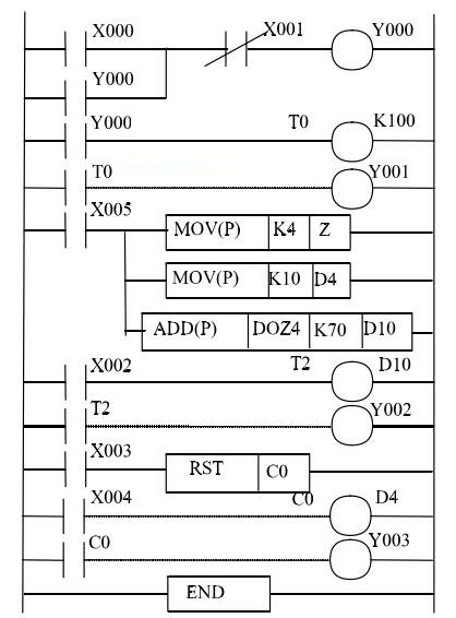
②Use the ladder diagram programming method to edit the ladder diagram program shown in Figure 1 and save it.
(3)Transmission of program.
①Write the program. Write the edited program into the PLC user memory RAM, and then check.
②Reading the program. Read the program in the PLC user memory into the computer through the [Read] operation, and then verify it.
③Procedure verification. During the above-mentioned program verification process, only when the programs on both ends of the computer are compared correctly can the program be considered to be transmitted correctly. Otherwise, the cause should be found out and re-transmitted.
2. Run the operation
After the program is transferred to the PLC user memory, the program can be run according to the following steps.
① According to the ladder diagram program, connect the input/output terminals of the PLC to the external input signals. The input/output terminal numbers and descriptions of the PLC are shown in Table 1.
② Turn on the PLC running switch and the RUN light on the PLC panel lights up, indicating that the program has been put into operation.
③ Combine with the control program, operate the relevant input signals, and observe the changes of the input/output indicator lights under different input states. If the status of the output indicator lights is consistent with the program control requirements, it indicates that the program is running normally.

Table 1 PLC input/output terminal numbers and descriptions

(2) Output forced ON/OFF. Perform forced OFF operations on Y000 and Y001, and perform forced ON operations on Y002 and Y003.
(3) Modify the current values of T, C, D, and Z.
① After changing the current value of Z K4 to K6, observe the running results and analyze the reasons for the change.
② Set the current value of D4, observe the running results, and analyze the reasons for the change.
(4) Modify the current values of T and C.
① After changing the setting value K100 of T0 to K150, observe the running results and write down the operation process.
② After changing the setting value D4 of C0 to K10, observe the operation results and write down the operation process.
The above is the detailed content of How to program and run Mitsubishi PLC programming software (GX Developer) - How to program and run Mitsubishi PLC programming software (GX Developer). For more information, please follow other related articles on the PHP Chinese website!


