
The camera acquires a frame of image in two stages: exposure and readout. Depending on the sensor used by the camera, the overlapping relationship between the camera's exposure time and readout time is also different, which can be divided into overlapping exposure and non-overlapping exposure.
Compared with non-overlapping exposure, overlapping exposure can reduce the impact of exposure time on the drawing time.
Rewritten sentence: After the exposure and readout of the current frame are completed, the exposure and readout of the next frame are performed. This is a non-overlapping exposure. The non-overlapping exposure frame period is greater than the sum of the exposure time and the frame readout time.

Inner trigger mode non-overlapping exposure
Overlapping exposure means that the exposure of the current frame partially overlaps with the readout process of the previous frame, that is, the exposure of the next frame has begun, while the readout of the previous frame is still in progress. The overlapping exposure frame period is less than or equal to the sum of the exposure time and the frame readout time.

Internal trigger mode overlapping exposure
Yes! The purpose of the previous paragraph is to tell you: don’t be surprised whether the exposure time of the current frame overlaps with the readout time of the previous frame in the following description.
The trigger mode of the camera is divided into two types: internal trigger mode and external trigger mode.
Internal trigger mode: The camera collects images through the signal given inside the device.
External trigger mode: The camera collects images through external signals. Soft trigger and hardware trigger are the two main forms of external signals. External signals can be either software signals or hardware signals. The external trigger mode is as shown in the figure:
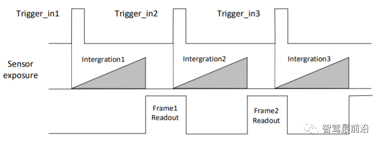
External trigger mode
Soft trigger : The trigger signal is sent by the software (you can also use the API interface provided by the camera SDK for soft triggering).
When using hardware trigger, the camera will connect to the external device through its I/O interface and receive the trigger pulse signal from the external device to collect images. In fact, it directly reads and writes the internal registers of the camera. The picture below is the 6-pin cable of the power IO of the Hikvision camera:
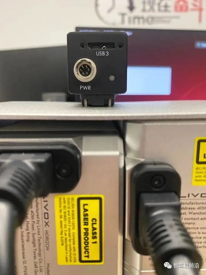
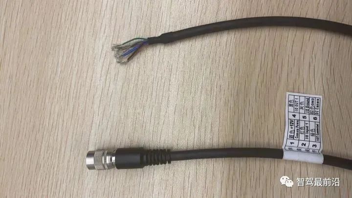
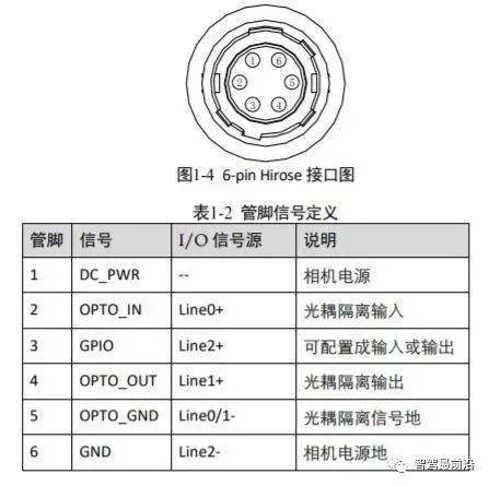
##Haikang camera power supply and IO interface (6-pin Hirose)
Among them, Hikvision camera has 1 optocoupler isolated input Line0 and 1 configurable input and output Line2, one of which can be selected as the input signal.
##Strobe signal pre-output timing Now let’s get back to the topic, it’s going to go really fast now.
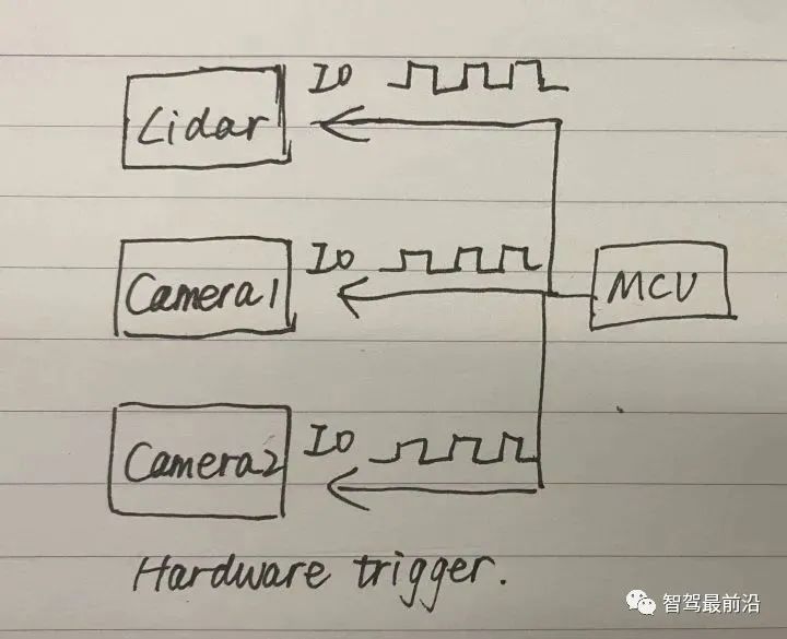
There are three main ways to synchronize camera and lidar timestamps: hard triggering, soft triggering, and soft triggering plus a hard trigger. Below I introduce them one by one in the form of a hand-drawn schematic diagram.
Let’s talk about hard trigger first. An MCU generates pulse signals to hard trigger three sensor devices.
#For soft triggering and hard triggering, you can first use the API of the camera SDK to soft trigger a camera, and then use the external trigger signal of the camera Strobe performs hard triggering on other sensors such as radar and cameras.
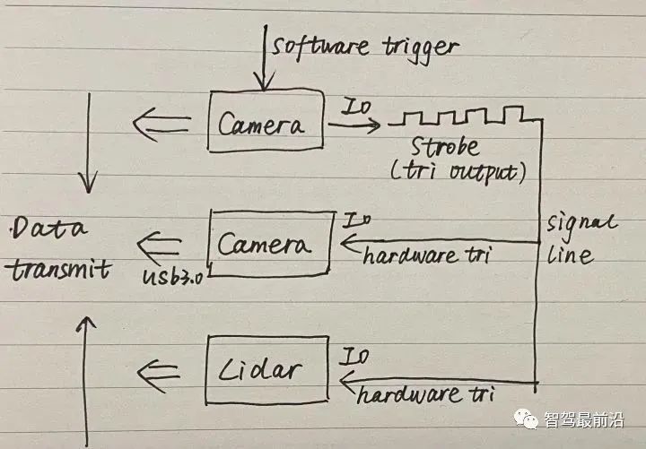
#There is a problem that needs to be noted here. If the first camera that is soft-triggered emits a Strobe signal at the same time as the exposure, the other sensors that are hard-triggered will After all, it is a step too late and cannot be completely synchronized. Therefore, the previously proposed concept of pre-output strobe is introduced, that is, strobe output is performed before delayed exposure.
Pay attention to four points when configuring this mode:
Finally Let’s talk about soft triggering which is not recommended.
The first call to the API operation is obviously slower than the hard trigger (direct read and write operations on the sensor's internal register). API(1) has already taken some time before executing the second command API(2). time.
<code>//读取lidar和image数据的线程1while(1){API(1); //软触发第一个sensorAPI(2); //软触发第二个sensor//假设脉冲周期为0.5s}//处理数据线程2for(i=0;i<nimage gettickcount t1 gettickfrequency></nimage></code>When the time required to process a single frame of data exceeds 0.5 seconds, thread 1 will read the next frame of data, causing the data of thread 2 to be confused. Thread 2 must complete processing of a single frame within 0.5 seconds and needs to wait after each frame (1/fps - current frame processing time).
The above is the detailed content of An article talks about the time stamp synchronization problem of lidar and camera calibration. For more information, please follow other related articles on the PHP Chinese website!
 What skills are needed to work in the PHP industry?
 Four major characteristics of blockchain
 How to clean the C drive when it turns red
 How to install printer driver in linux
 mom.exe initialization error
 How to introduce external css into html
 Tutorial on buying and selling Bitcoin on Huobi.com
 Free data recovery software


