
For the next generation of centralized electronic and electrical architecture, the use of central zonal central computing unit and regional controller layout has become a must-have option for various OEMs or tier1 players. Regarding the architecture of the central computing unit, there are three ways : Separate SOC, hardware isolation, software virtualization. The centralized central computing unit will integrate the core business functions of the three major domains of autonomous driving, smart cockpit and vehicle control. The standardized regional controller has three main responsibilities: power distribution, data services, and regional gateway. Therefore, the central computing unit will integrate a high-throughput Ethernet switch.
As the degree of integration of the entire vehicle becomes higher and higher, more and more ECU functions will slowly be absorbed into the regional controller. The platform-based regional controller uses the same hardware design and the same IO interface, which can better meet the scalability requirements of different models. Therefore, regional control also assumes the important function of vehicle hardware abstraction. The two will use high-speed Ethernet instead of the original Can communication to connect to each other. In summary, the scalable electronic architecture is to shield the hardware differences between models. No matter how many regional controllers are used in the communication network, their mutual communication modes follow the same rules. At the same time, the regional controller also assumes the responsibility of abstracting the ECU functions within its local area network.
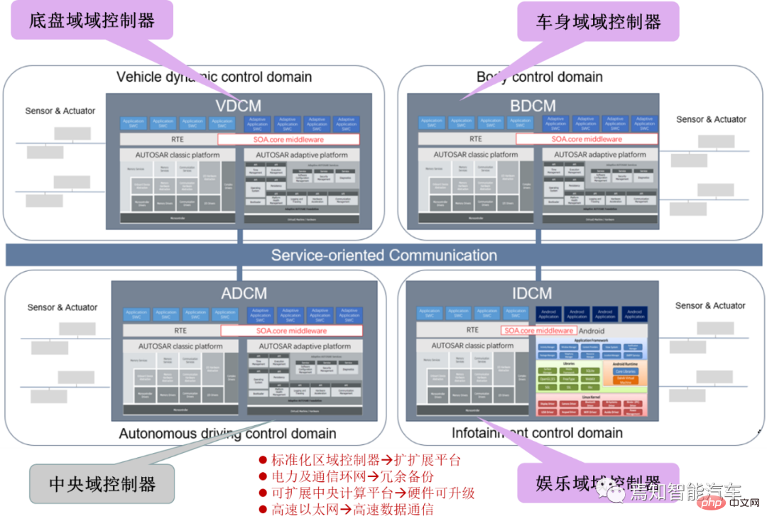
The above centralized architecture with the central computing platform as the core has set up a unified sensor and peripheral interface, which can support chip upgrades. Its ultimate goal is to achieve in-car Hardware during the life cycle can be upgraded, thereby extending the intelligent life cycle of the car. Each regional controller has its own operating system middleware SOA Core Middleware, which can provide a distributed computing and communication framework, shield the differences in the kernels of various operating systems, and provide a unified service development framework for the upper side. Functions involved include service management, network management, communication management, upgrades, diagnosis, logs, status, etc.
This article will focus on the direction of software and hardware decoupling to explain how to deploy software and hardware for SOA.
The following figure shows the typical SOA software architecture design principle. This service-oriented development architecture is actually an SOA architecture model solution for service-oriented development, allowing product managers to focus on service design, while system software goes deep into the product development process. This is also a solution to the automotive software crisis. A major breakthrough. The entire SOA architecture can be summarized as a software-hardware decoupled system built by a logical architecture and service abstraction and adaptation completed by a service architecture, ultimately establishing a standardized service system.
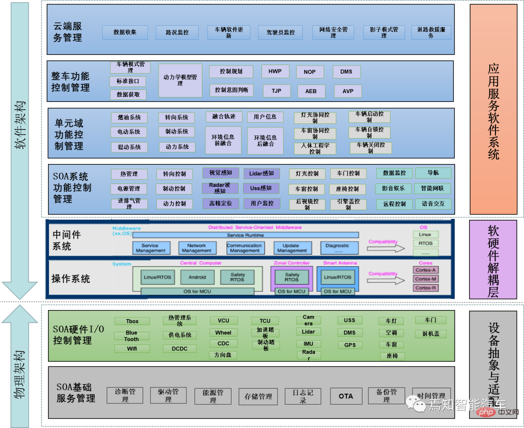
The overall logical architecture design process can be summarized as:
Electronic and electrical architecture: Design an scalable architecture (also called computing and communication architecture) need to meet the requirements of layered design, layered testing, and layered verification to avoid the chain reaction of software changes during the development phase and the concentrated outbreak of problems during integration testing, so that problems can be discovered more quickly and software versions can be changed more quickly.
Hardware computing platform: The scalable hardware platform includes SOA basic service management and SOA hardware I/O control management. It is compatible with multiple sensors and external devices of the autonomous driving system and supports multiple Heterogeneous chips and hardware upgrades.
Operating system kernel/service middleware:As the core of file scheduling and driving, the operating system can achieve the best control in supporting software and hardware decoupling and software deployment on hardware ability.
Communication architecture: The scalability of the communication architecture can well ensure rapid adaptation in the development of platform-based models. The differences between models can be reduced to a minimum, and the order of the next stage of model development can be ensured. By drawing on the current generation of products for communication expansion, there is no need to carry out a lot of additional development work, which can greatly reduce the pressure of later product line maintenance.
In order to meet the real-time requirements of vehicle control, the core network will adopt reliable communication technologies such as TSN. In the LAN under the regional controller, traditional communication methods such as CAN and Lin will continue to exist. Communication within the local area network can be carried out in the form of traditional signals. In the core Ethernet backbone network, data will be interacted with in the form of services, which requires communication middleware such as DDS.
Service layer/application layer: The standardized service layer and orchestratable application layer include SOA system function management, unit domain function management, vehicle function control management, and cloud service management. important part.
Before a detailed analysis of the deployment of core technologies in a software architecture with central domain control as the core, detailed analysis is required. Explain some important related concepts. The sensor/actuator design pattern in Autosar describes how the ECU handles the sensors/actuators in the loop in the context of the overall architecture.
BEG device abstraction is located on RTE (on top of the trial run environment). It is a set of software components abstracted from the sensors and actuators connected to a specific ECU. It uses sensor or actuator software components and is RTE The only component above that allows access to the ECU abstract interface. Device abstraction extracts the raw signals of sensors and actuators, such as pixels, point clouds, voltages, PWM signals, digital signals/messages, frequencies, and provides physical interfaces (such as pixels, point clouds, pressure, mass, Temperature, etc.). Actually, the device abstraction completes the conversion of physical values such as voltage values, digital signals, point clouds, etc.
Device abstraction reflects the interchangeability of application layer software between different hardware variants through platform software and underlying driver software.
Table 1 Abstract relationship between platform software and equipment (sensor)
| Abstract layering |
Function |
Working principle |
Working details |
Platform software |
Input original acquisition value, output voltage value Decoupling software and hardware connection |
Provide physical properties original interface |
Mechanical properties, electrical properties, functional properties and procedural properties. |
Electrical equipment driver |
Input voltage value, output filtered voltage value Ensure sensor Measured value availability |
Run electrical device driver software electrical diagnostics (such as detecting ground, battery short circuit, open circuit, etc.) |
Denoising filter Voltage compensation when the sensor is externally powered |
Sensor device driver |
Input voltage value, output sensor value such as pixel, point cloud, temperature value Decoupling different sensor differences |
Execute the sensor device driver; Control the physical behavior of the sensor; |
·Conversion from raw signal (electrical signal) to physical value; ·Zero point and offset adaptation ·Drift detection of measured values ·Diagnostic check ·Physical value check ·Filtering function (including downsampling) |
Virtual device driver |
Input the meaning value of the sensor and output the complete value after the supplement, such as the brightness value Decoupled sensor signal compensation terminal |
The virtual device driver of the sensor is abstracted by its physical representation of the software program |
·Signal quality evaluation ·Replacement of the original value of the signal (such as when the sensor signal quality is insufficient) ·Signal original value compensation ·Signal original value verification ·Functional test diagnostic interface |
Table 2 Abstract relationship between platform software and device (executor)
| ##Abstract layering | Function | Working principle | Work Details |
| Platform software | Input PWM, output PWM valueDecoupling software and hardware Connection | Provides physical properties raw interface | Mechanical properties, electrical properties, functional properties and procedural properties. |
| Electronic device driver | Input voltage value, output filtered voltage valueEnsure execution Validity of the device execution process | Run the electrical equipment driver software electrical diagnosis (such as detecting short circuit to ground, battery, open circuit, etc.) | Denoise FilterVoltage compensation when the actuator is externally powered |
| Actuator device driver | Input PWM, output protection and corresponding PWM valueDecoupled execution of mechanical processDecoupled actuator capability protection
|
The sensor device driver represents the physical behavior of the actuator |
·Superimpose the output value to overcome the friction of the driver ·Output execution signal value and ensure effective execution ·Limit the output value to prevent excessive damage ·Control the set value (with sensor data closed loop) ·Provide limit and capability information Interface |
Virtual device driver |
Input the actuator request value and output the PWM value, such as valve opening Decoupling the processing of executor jitter, non-linearization, execution overrun, etc. |
The physical representation of the abstract executor of the virtual device execution program |
·Conversion of physical request values on the control side ·Conversion of non-linear values into linear values ·Diagnostic tester interface for functional testing ·Special mode processing ·Start the actuator to run ·Eliminate the phased jitter of the actuator by overwriting the set value or filtering ·Coordinate the actuator Safe activation |
In summary, the abstract concept and design of the BEG device can be summarized as follows:
The application software is independent of the specific sensors and actuators connected to a specific ECU;
Between different sensors and actuators Code can be reused;
Different code sharing cooperation models (software sharing), thereby supporting different business models;
Deploy or redistribute functions to different ECUs;This design pattern Also known as device abstraction;
Device abstraction solves the problem of S&A layer Module exposing functions and service interfaces upwards, and connecting platform software downwards. The goal is to expose interfaces as much as possible, achieve software and hardware decoupling, and avoid S&A Changes result in software changes.
Here we give an example to illustrate how to implement device abstraction in SOA architecture. This method only needs to know the sensor category (such as radar, camera, etc.) to define the input raw data Rawdata. There is no need to know the specific connection method of these sensors. For the top application layer, only the final sensing data needs to be applied.
Taking the device abstraction of the sensor as an example, it can be expressed as follows:
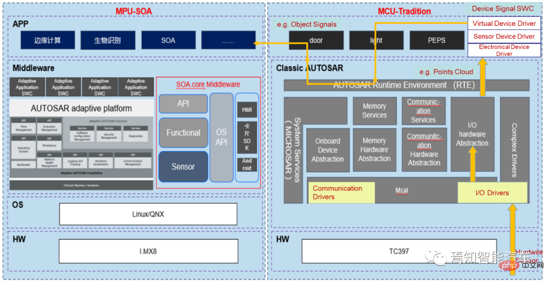
First, MCAL in the underlying physical layer collects data by accessing the uC port and Provide raw data and detect it every certain period (such as 10ms). There is no need to understand the connection mode of electrical appliances and the corresponding data meaning. For example, the original image pixel data is collected from the underlying lidar sensor and input to the microcontroller MCU/SOC.
Secondly, the MCU/SOC takes out the corresponding point cloud value from the corresponding physical address according to a certain period, gives it to the I/O hardware abstraction module through the I/O device, and measures it through the I/O hardware abstraction point detection The first-level electrical appliances at the data measurement point are connected to the routing. The sensor calculates the voltage value based on the routing information and the interpreted raw data and performs filtering processing. This process does not require understanding the meaning of the measured data.
Subsequently, the voltage value in the hardware abstraction module is processed step by step according to the 8bit driver, and is called by the sensor electronic device driver to generate the basic original value. This value drives the Virtual Device Dri through the sensor virtual device pedestrians, road signs, etc.
Finally, the application software in AP Autosar reads the sensor sensing target-level data in real time through the real-time running environment RTE, which is used for subsequent planning control and decision-making control of the application software.
As can be seen from the above example, device abstraction has the following advantages. Changes in Sensor & Actuator will not cause associated changes in platform software and application software. In summary, there are roughly the following types of software and hardware decoupling caused by transformations. 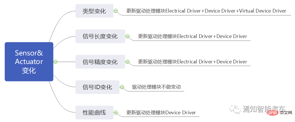
For replacing different models of sensing sensors, the selection of ECU is no longer limited to the signal analysis mode model supported by the ECU. For example, to replace NTC and PTC models, you only need to modify the software module located in the Device Driver.
Sensors and actuator modules of the same type can share some of the same processing modules. For example, for the processing mode of the side-view camera, the processing algorithm of one of the side-view cameras can be directly applied to the other three. , and only need to recalibrate the camera parameters of the three cameras. If some cameras need to be updated to higher resolution cameras, there is no need to make major changes to the underlying driver software and platform software, at least There is no need to change the I/O interface form and data input mode. Only the algorithm module for processing images needs to be re-tuned. For example, the original low-resolution processing algorithm may not meet the real-time requirements of the high-resolution processing module. , at this time, it is necessary to study the optimization method of the neural network acceleration model, but the overall algorithm architecture model remains unchanged.
Currently, the development method advocated by many OEMs is to carry out platform product development, and platformization emphasizes the core idea of decoupling software and hardware. The adoption of SOA architecture model is It is convenient to form a division of labor between product lines and platform lines. The product line is responsible for specific vehicle model projects, and the platform line is responsible for building a technical center. In the development of new platforms, the technical links are often very long and complex. The layered architecture design and software and hardware decoupling method can facilitate layered testing and verification, reduce the pressure of integration testing, and discover problems more fully. , can also increase the speed of version release.
The above is the detailed content of Software architecture design and software and hardware decoupling methodology in SOA. For more information, please follow other related articles on the PHP Chinese website!


