Home >Common Problem >How to mark surface roughness in CAD
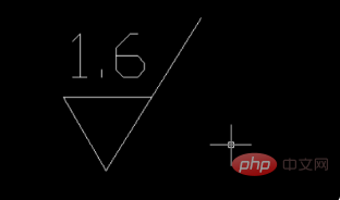
How to mark surface roughness in CAD: first set up polar tracking and set a 30-degree angle as shown in the diagram; then draw the first edge, paying attention to tracking the angle; finally follow the example of the diagram to draw another aside.

The operating environment of this article: Windows 7 system, autocad2020 version, Dell G3 computer.
How to mark surface roughness in CAD:
1. First, we need to set up polar axis tracking in order to draw standard graphic symbols - click on the polar axis - settings .

#2. Set the 30-degree angle as shown in the figure - OK.

#3. Draw the first edge, pay attention to tracking the angle, the length is not limited.
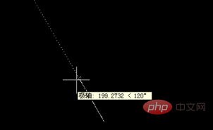
#4. Follow the example to draw the other side.
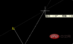
5. Draw the last side.
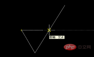
6. Add text
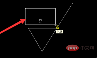
#7. The effect is as shown in the picture. You can use the sc command to zoom in and out to the desired size. Just change the value for different sizes and roughness.
##Related video recommendations:
The above is the detailed content of How to mark surface roughness in CAD. For more information, please follow other related articles on the PHP Chinese website!