
The content of this article is about the implementation (code) of how to use the Chrome console to edit 3D models. The content is very detailed. Friends in need can refer to it. I hope it can help you.
Foreword: The core of 3D model editing is the editing of vertex positions and texture colors. The purpose of this research is to find a method to directly edit the model through programming. This editing method is similar to the popular mouse click method. , the relationship between the drag-and-drop editing method is very similar to the relationship between "programmers write static web pages" and "artists cut web pages" in front-end programming.
1. Tool usage:
1. Visit https://ljzc002.github.io/SnowMiku/HTML/MakeRibbon.html to open the strip grid generator page

There is a green ball at (0,-10,0), (0,0,0), (0,10,0) of the scene world coordinate system as a reference point. , use up, down, left, right and mouse drag to roam the scene.
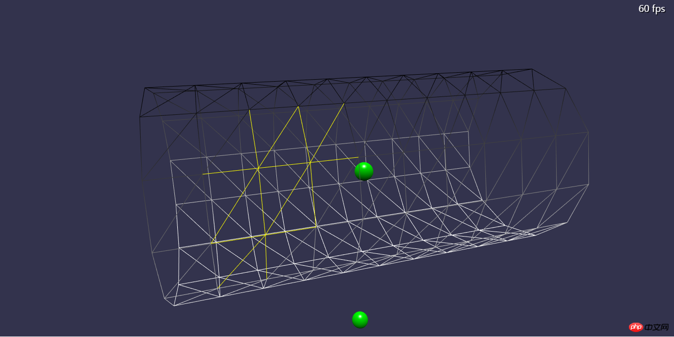
2. Press the F12 key to open the Chrome console, enter in the console: MakeRibbon(MakeRing(5,12),-10,2,11,"mesh_ribbon") and press Enter:
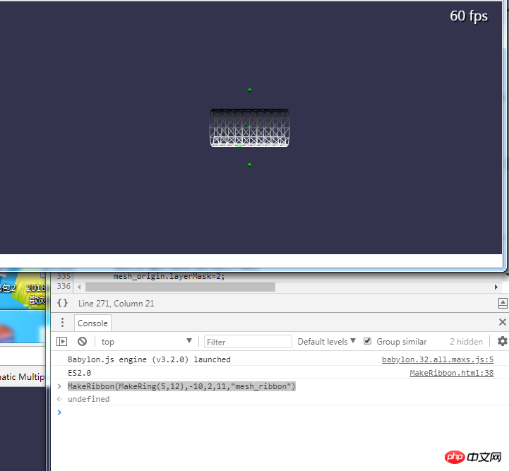
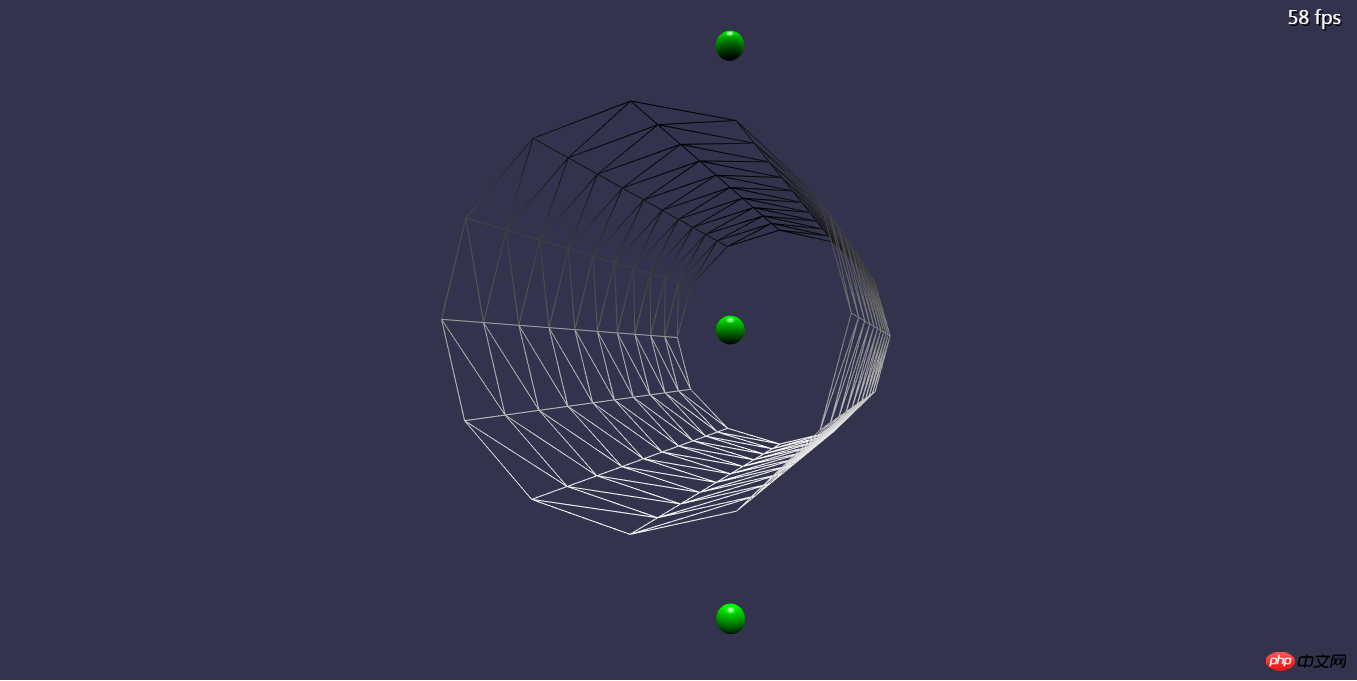
A cylindrical surface with a radius of 5, a surface subdivision of 12, a left end at -10, a distance of 2 between each ring, and a total of 11 rings is drawn in the scene.
Zoom in to view:
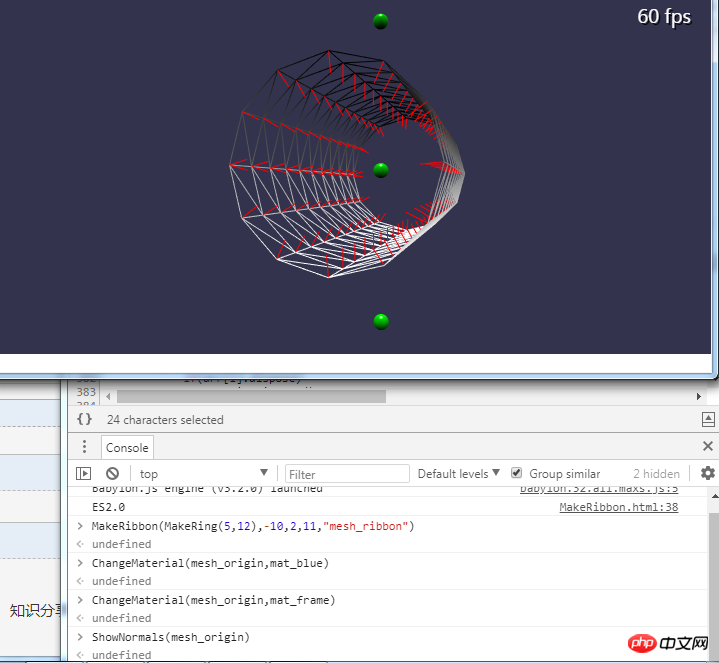
3. Enter ShowNormals(mesh_origin) to display the normal direction of each vertex with a red line segment
Enter DeleteMeshes([lines_normal]) to delete all normals, and enter DeleteMeshes([mesh_origin]) to delete the cylindrical mesh.
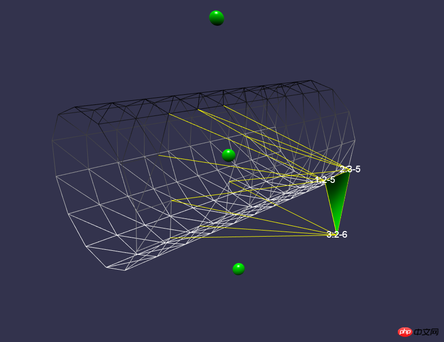
4. Move the mouse into a triangle on the grid, and the vertex information of the triangle will be displayed:
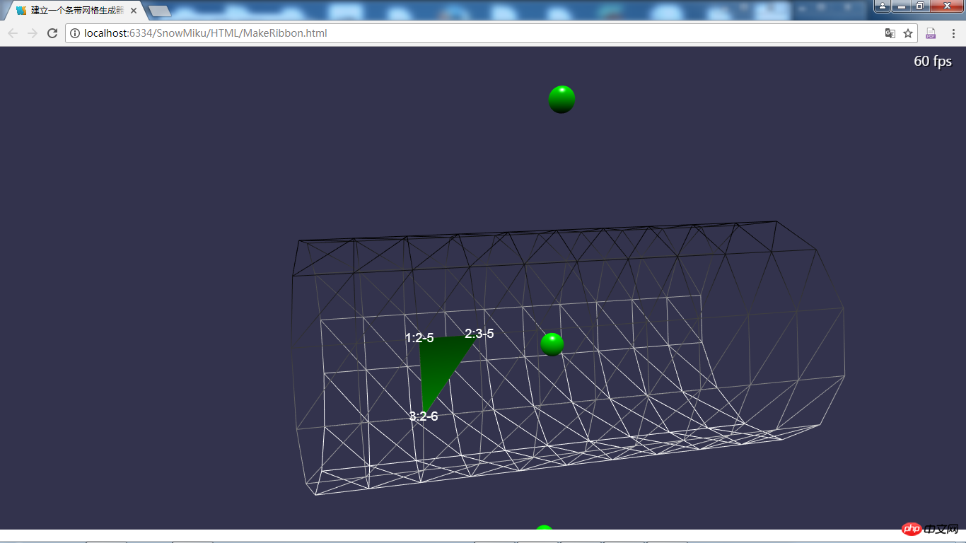
where "1:2-5" means that this is a triangle The first vertex of , this vertex is located on the ring with index 2 (the third ring), and the index of this vertex in the ring is 5 (that is, the sixth vertex).
5. Enter PickPoints([[2,5],[3,5],[2,6]],mesh_origin) to select these vertices
All border lines affected by the selected vertices are marked in yellow. This "select" only changes the appearance.
6. Enter TransVertex(mesh_origin,arr_ij,BABYLON.Matrix.Translation(0,0,-10)) to move the selected vertex 10 in the negative direction of the z-axis. The moved vertex is the same as the previously selected one. The vertices actually don't matter. arr_ij can also be directly replaced by the index array [[2,5],[3,5],[2,6]].
Another type of deformation can be achieved by inputting: TransVertex(mesh_origin,arr_ij,BABYLON.Matrix.RotationX(Math.PI/2)), which can convert the selected The vertex is rotated 90 degrees around X.
Enter DeleteMeshes([lines_inpicked]) to cancel the selected effect, enter ChangeMaterial(mesh_origin,mat_blue) to replace the border with a blue texture:

Yes After seeing the deformed effect, you can continue to select the vertices and deform
7. Enter ExportMesh("1",mat_blue) to export the babylon model file in txt format, with the file name "1.txt"

8. Rename the exported txt to 9.babylon and put it in the website directory. Visit https://ljzc002.github.io/SnowMiku/HTML/LoadBabylon. html model preview page, enter ImportMesh("","../ASSETS/SCENE/","9.babylon") in the console to load the model just exported.
2. Programming ideas:
1. First, we must establish a basic scene that can be used for various tests. The code used is as follows:
建立一个条带网格生成器,能够输入参数生成起始条带,然后通过命令行选取并修改pathArray,最后导出生成的条带
This 3D scene includes simple Some basic elements required for testing are used here. The uncompressed version of Babylon.js library containing all components is used. In order to save bandwidth in actual use, you can use the tools provided by Babylon.js official website to customize a streamlined or compressed version of Babylon. .js library
2. Create a basic mesh
The plan is to generate various simple models by performing vertex transformation on a basic mesh. In Babylon.js, "strips" " is a mesh type that is very suitable for vertex transformation. There are documents about strip construction and deformation in the official Babylon.js tutorial. You can download the Chinese translation here http://down.51cto.com/data/2449757.
The code used to establish the basic grid is as follows:
//下面这些函数都通过控制台调用 //在ZoY平面里建立一个圆环路径 //radius:半径,sumpoint:使用几个点 function MakeRing(radius,sumpoint) { var arr_point=[]; var radp=Math.PI*2/sumpoint; for(var i=0.0;i

         Copy after login
Several problems encountered in programming:
a. The coordinate values set in the path are actually displayed when Small changes may occur, for example, 5 may become 4.9999999999999999999, but it seems to have no effect.
b、虽然圆环路径分成12段应该由12个顶点组成,但是如果只有12个顶点,那么在调用CreateRibbon方法时,如果把closePath参数设为true则Babylon.js会自动添加一个不受控制的顶点来闭合圆环路径,如果设为false,则路径无法闭合。为此在第18行再添加一个与起始点
重合的顶点使圆环路径闭合。
c、原计划直接使用数组的concat方法复制arr_point数组产生更多的圆环路径,但concat方法似乎只能对一维数组使用(栈?),而arr_point的每个元素都是一个BABYLON.Vector3对象,所以只好用for循环一个点一个点的生成路径
d、MakeRing是一个生成圆环路径的方法,使用者可以根据需要编写各种其他类型的路径生成方法。
3、调整网格的属性:
可以对网格的属性进行一些调整,但是这些调整只在这个编辑器里生效,并不会被导出。
比如对网格材质的调整:
function ChangeMaterial(mesh,mat) { mesh.material=mat; }
4、显示网格顶点法线方向
代码如下:
var lines_normal={}; /*ShowNormals(mesh_origin) DeleteMeshes([lines_normal]); * */ //显示所有的顶点法线 function ShowNormals(mesh) { //DeleteMeshes(arr_line_normal); if(lines_normal.dispose) { lines_normal.dispose(); } //遍历顶点 var vb=mesh.geometry._vertexBuffers; var data_pos=vb.position._buffer._data;//顶点数据 var data_mormal=vb.normal._buffer._data;//法线数据 var len=data_pos.length; var lines=[]; for(var i=0;i

         Copy after login
Babylon.js内置的CreateLineSystem方法可以方便的建立一个由很多条线段组成的网格。
5、删除网格
代码如下:
function DeleteMeshes(arr)//假设一个数组里的都是mesh,彻底清空它 { var len=arr.length; for(var i=0;i

         Copy after login
值得注意的是,直接在控制台里执行mesh.dispose()并不生效。
这里也体现出CreateLineSystem的方便之处——删除法线时只需要dispose一个对象。
6、鼠标移入时显示三角形信息
鼠标动作监听代码:
mesh_origin=new BABYLON.Mesh("mesh_origin",scene);//建立一个空的初始网格对象 mesh_surface=new BABYLON.Mesh("mesh_surface",scene); mesh_surface0=new BABYLON.Mesh("mesh_surface0",scene); if(true) {//初始化三个GUI标签 label_index1=new BABYLON.GUI.TextBlock(); label_index1.text = "label_index1"; label_index1.color="white"; label_index1.isVisible=false;//初始化时标签不可见 //label_index1.linkWithMesh(mesh_surface0);//TextBlock并不是顶层元素 advancedTexture.addControl(label_index1); label_index2=new BABYLON.GUI.TextBlock(); label_index2.text = "label_index2"; label_index2.color="white"; label_index2.isVisible=false; //label_index2.linkWithMesh(mesh_surface0); advancedTexture.addControl(label_index2); label_index3=new BABYLON.GUI.TextBlock(); label_index3.text = "label_index3"; label_index3.color="white"; label_index3.isVisible=false; //label_index3.linkWithMesh(mesh_surface0); advancedTexture.addControl(label_index3); } //监听鼠标移动 canvas.addEventListener("mousemove", function(evt){ var pickInfo = scene.pick(scene.pointerX, scene.pointerY,null,null,camera0);//如果同时有多个激活的相机,则要明确的指出使用哪个相机 //cancelPropagation(evt); //cancelEvent(evt); label_index1.isVisible=false; label_index2.isVisible=false; label_index3.isVisible=false; if(mesh_surface.dispose) { mesh_surface.dispose(); } if(mesh_surface0.dispose) { mesh_surface0.dispose(); } if(pickInfo.hit&&(pickInfo.pickedMesh.name=="mesh_origin"||pickInfo.pickedMesh.name=="mesh_ribbon"))//找到鼠标所在的三角形并重绘之 { //在鼠标所指的地方绘制一个三角形,表示被选中的三角形 var faceId=pickInfo.faceId; var pickedMesh=pickInfo.pickedMesh; var indices=[pickedMesh.geometry._indices[faceId*3] ,pickedMesh.geometry._indices[faceId*3+1],pickedMesh.geometry._indices[faceId*3+2]]; var vb=pickedMesh.geometry._vertexBuffers; var position=vb.position._buffer._data; var normal=vb.normal._buffer._data; var uv=vb.uv._buffer._data; var len=arr_path[0].length; var p1={index:indices[0],position:[position[indices[0]*3],position[indices[0]*3+1],position[indices[0]*3+2]] ,normal:[normal[indices[0]*3],normal[indices[0]*3+1],normal[indices[0]*3+2]] ,uv:[uv[indices[0]*2],uv[indices[0]*2+1]],ppi:("1:"+(Math.round(indices[0]/len)+0))+"-"+(indices[0]%len)};//pathpointindex var p2={index:indices[1],position:[position[indices[1]*3],position[indices[1]*3+1],position[indices[1]*3+2]] ,normal:[normal[indices[1]*3],normal[indices[1]*3+1],normal[indices[1]*3+2]] ,uv:[uv[indices[1]*2],uv[indices[1]*2+1]],ppi:("2:"+(Math.round(indices[1]/len)+0))+"-"+(indices[1]%len)}; var p3={index:indices[2],position:[position[indices[2]*3],position[indices[2]*3+1],position[indices[2]*3+2]] ,normal:[normal[indices[2]*3],normal[indices[2]*3+1],normal[indices[2]*3+2]] ,uv:[uv[indices[2]*2],uv[indices[2]*2+1]],ppi:("3:"+(Math.round(indices[2]/len)+0))+"-"+(indices[2]%len)}; var po=[(p1.position[0]+p2.position[0]+p3.position[0])/3,(p1.position[1]+p2.position[1]+p3.position[1])/3,(p1.position[2]+p2.position[2]+p3.position[2])/3]; var numm=2; mesh_surface0=newland.make_tryangle(p1,p2,p3,"mesh_surface1",scene);//使用三个点绘制一个三角形 mesh_surface0.material=mat_green; mesh_surface0.sideOrientation==BABYLON.Mesh.DOUBLESIDE; mesh_surface0.layerMask=2; label_index1.isVisible=true; //label_index1.layerMask=2;//这个属性对于gui被管对象并不生效? label_index1.text=p1.ppi;//ppi表示这个顶点是三角形的第几个顶点,以及这个顶点位于第几条路径的第几个位置 var pos1=new BABYLON.Vector3(p1.position[0],p1.position[1],p1.position[2]); label_index1.moveToVector3(pos1,scene); label_index1.itspos=pos1; label_index2.isVisible=true; label_index2.text=p2.ppi; var pos2=new BABYLON.Vector3(p2.position[0],p2.position[1],p2.position[2]); label_index2.moveToVector3(pos2,scene); label_index2.itspos=pos2; label_index3.isVisible=true; label_index3.text=p3.ppi; var pos3=new BABYLON.Vector3(p3.position[0],p3.position[1],p3.position[2]); label_index3.moveToVector3(pos3,scene); label_index3.itspos=pos3; //将三个点移动到场景的中心 pt=[(p1.position[0]-po[0])*numm,(p1.position[1]-po[1])*numm,(p1.position[2]-po[2])*numm]; p1.position=pt; pt=[(p2.position[0]-po[0])*numm,(p2.position[1]-po[1])*numm,(p2.position[2]-po[2])*numm]; p2.position=pt; pt=[(p3.position[0]-po[0])*numm,(p3.position[1]-po[1])*numm,(p3.position[2]-po[2])*numm]; p3.position=pt; //在场景的中心再绘制一个大一倍的三角形 mesh_surface=newland.make_tryangle(p1,p2,p3,"mesh_surface",scene); mesh_surface.material=mat_green; mesh_surface.sideOrientation==BABYLON.Mesh.DOUBLESIDE; mesh_surface.layerMask=1;//遮罩层次是1 } },false);
需要注意的有以下几点:
a、鼠标指向时显示的是这个点在arr_path中的索引,而不是在“顶点数据对象”中的索引!
b、最初的计划是像魔兽争霸3一样在窗口的左下角建立一个遮罩层次为1的小视口,用来特写被选中的三角形(mesh_surface),但是后来发现Babylon.js的GUI不能设置遮罩层次,也不能像鼠标选取一样设置相对于哪一个相机,所以取消了左下角的小视口。
如果需要添加视口,代码如下:
var mm = new BABYLON.FreeCamera("minimap", new BABYLON.Vector3(0,0,-20), scene); mm.layerMask = 1; var xstart = 0.0, ystart = 0.1;//意为占屏幕宽高的比例 var width = 0.2, height = 0.2; //视口边界从左下角开始 mm.viewport = new BABYLON.Viewport( xstart, ystart, width, height ); scene.activeCameras.push(mm);var mm = new BABYLON.FreeCamera("minimap", new BABYLON.Vector3(0,0,-20), scene); mm.layerMask = 1; var xstart = 0.0, ystart = 0.1;//意为占屏幕宽高的比例 var width = 0.2, height = 0.2; //视口边界从左下角开始 mm.viewport = new BABYLON.Viewport( xstart, ystart, width, height ); scene.activeCameras.push(mm);
c、需要注意的是GUI是一次性绘制在视口上的,默认情况下即使相关的网格位置发生变化,GUI仍然会保持在视口上最初的位置。linkWithMesh方法可以将GUI和网格绑定起来,但是似乎只能对部分“底层的”GUI类型生效,为了使得标签跟随顶点移动,需要手动在每一帧渲染之前更新标签的位置:
scene.registerBeforeRender(function() { if(scene.isReady()) { if(label_index1.isVisible==true)//不断刷新gui的位置 {//在具有多个激活相机时选择了错误的参考相机?-》会强制选择最新建立的相机 label_index1.moveToVector3(label_index1.itspos,scene); label_index2.moveToVector3(label_index2.itspos,scene); label_index3.moveToVector3(label_index3.itspos,scene); } } });
7、选取顶点:
3DsMax和Blender(Babylon.js库在3D模型部分参考了Blender的许多设计)都使用鼠标在网格中选取需要修改的区域,我不是很习惯这种方式,所以考虑用JS函数代替鼠标操作:
var lines_inpicked={};//线段系统对象,表示所有被选中点影响的线段 var arr_ij=[];//记录被选中的点在arr_path中的索引的数组 /*DeleteMeshes([lines_inpicked]); * PickPoints([[0,0],[0,12],[1,1]],mesh_origin) * */ //选定一些顶点 function PickPoints(arr,mesh) { if(arr_path.length==0) { alert("尚未生成路径数组!"); return; } if(lines_inpicked.dispose) { lines_inpicked.dispose(); } //arr_ij=[]; //为了后面考虑,需要先对arr整体遍历一遍,把首尾接口处关联起来 arr_ij=arr;//把路径和点的位置记录下来 var vb=mesh.geometry._vertexBuffers; var data_pos=vb.position._buffer._data; var len_pos=data_pos.length; var data_index=mesh.geometry._indices; var len_index=data_index.length; var len=arr.length; var lines=[]; for(var i=0;i

         Copy after login
有以下几处需要注意:
a、因为MakeRing生成的路径里包括两个重合的点(首尾),为了保证变形后的网格仍然连续,在选择时这两个重合的点必须同时被选中,经过考虑,规定这个确保首尾重合点同时选中的操作在生成arr数组参数时进行。
b、因为基础网格mesh_origin的每一个顶点恰好位置不同,所以一开始我以为“与被选中的点的位置相同的点”应该具有与被选中点相同的变形效果,但是事实上经过网格变形后,完全可能出现两个不相干的顶点位于同一位置的情况,这时应用相同的变形效果会出现错误,比如人可以把手放在腿上,这时手和腿的接触点具有相同的位置,但如果因此对这两个点应用相同的变形效果,就很诡异了。同时如前文所说,有时arr_path中存储的位置和顶点数据中存储的位置可能出现微小的偏差。
最后采取的方法是将arr_path中的数组转化为顶点数据对象中的数组。
c、这里直接选取了几个点进行变形,还需要编写一些按照某种规则批量选取点的方法,也希望大家能帮我想一想怎样选取顶点比较方便。
8、网格变形:
代码如下:
/* * TransVertex(mesh_origin,arr_ij,BABYLON.Matrix.RotationX(Math.PI/2)) *TransVertex(mesh_origin,arr_ij,BABYLON.Matrix.Translation(0.5,0,0)) * */ //移动选定的顶点,同时更新网格、选取线、法线 function TransVertex(mesh,arr,matrix) { var len=arr.length; for(var i=0;i

         Copy after login
其实这里移动的顶点和前面选择的点没有关系,不选择也可以直接变形,只不过不会有黄线显示罢了。这里也同样需要一些生成更复杂的变换矩阵的方法。
9、导出:
导出方法的调用如下:
/*ExportMesh("1",mat_blue)*/ function ExportMesh(filename,mat) { try{ newland.ExportBabylonMesh([mesh_origin],filename,mat); } catch(e) { console.error(e) } }
函数的第一个参数是导出后的文件名(不包括扩展名),第二个参数是网格使用的材质对象(暂时只支持简单的颜色材质)。
其中ExportBabylonMesh是我编写的newland库中的一个方法,这个方法在前面关与3D模型的文章中也有提到过(https://www.cnblogs.com/ljzc002/p/6884252.html),这个方法整体上没有太大的改变。但是在旧版的Babylon.js中,顶点数据对象中的data属性是数组类型(?),而在新版中data属性则是typedArray类型,虽然这两种数据类型看起来很像,但在使用JSON.stringify(arr)转化为JSON字符串时,对于同样的数据[1,2,3],前者会转化为"[1,2,3]"后者则是"{"0":1,"1":2,"2":3}"!
在导入模型文件时后者会报错:“attempt to access out of range vertices in attribute 0”,这意味着在导入模型时顶点数据数组没有正确的载入,我的解决方案是导出前将data属性强制转化为数组类型:
//将TypedArray转化为普通array newland.BuffertoArray2=function(arr) { var arr2=[]; var len=arr.length; for(var i=0;i

         Copy after login
对于旧版的Babylon.js应该可以不加修改的使用这个方法,因为typedArray也具有数组的大部分功能。
10、导入:
在另一个页面里实现模型导入功能,这个页面同样在“基础场景”的基础上编写,其中导入方法如下:
function ImportMesh(objname,filepath,filename) { BABYLON.SceneLoader.ImportMesh(objname, filepath, filename, scene , function (newMeshes, particleSystems, skeletons) {//载入完成的回调函数 if(mesh_origin&&mesh_origin.dispose) { mesh_origin.dispose(); } mesh_origin=newMeshes[0]; //mesh_origin.material=mat_frame; //mesh_origin.layerMask=2; } ); }
相关推荐:
The above is the detailed content of Implementation of how to use Chrome console for 3D model editing (code). For more information, please follow other related articles on the PHP Chinese website!


![[Web front-end] Node.js quick start](https://img.php.cn/upload/course/000/000/067/662b5d34ba7c0227.png)