In visual navigation systems, lane detection is a crucial function. It not only has a significant impact on applications such as autonomous driving and advanced driver assistance systems (ADAS), but also plays a key role in the self-positioning and safe driving of smart vehicles. Therefore, the development of lane detection technology is of great significance to improving the intelligence and safety of the traffic system.
However, lane detection has unique local patterns, requires accurate prediction of lane information in network images, and relies on detailed low-level features to achieve precise localization. Therefore, lane detection can be considered as an important and challenging task in computer vision.
Using different feature levels is very important for accurate lane detection, but the discounting work is still in the exploratory stage. This paper introduces the cross-layer refinement network (CLRNet), which aims to fully exploit high-level and low-level features in lane detection. First, by detecting lanes with high-level semantic features, and then refining based on low-level features. This approach can utilize more contextual information to detect lanes while utilizing local detailed lane features to improve positioning accuracy. In addition, the feature representation of lanes can be further enhanced by collecting global context through ROIGather. In addition to designing a completely new network, a line IoU loss is also introduced, which regresses lane lines as a whole unit to improve positioning accuracy.
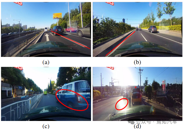
As mentioned earlier, since Lane has high-level semantics, but it has specific local patterns, detailed low-level features are required to accurately locate it. How to effectively utilize different feature levels in CNNs remains a problem. As shown in Figure 1(a) below, landmarks and lane lines have different semantics, but they share similar characteristics (e.g., long white lines). Without high-level semantics and global context, it is difficult to distinguish between them. On the other hand, regionality is also important, the alleys are long and thin, and the local pattern is simple.

The detection results of advanced features are shown in Figure 1(b). Although the lane is successfully detected, its accuracy needs to be improved. Therefore, combining low-level and high-level information can complement each other, resulting in more accurate lane detection.
Another common problem in lane detection is the lack of visual information of lane existence. In some cases, lanes may be occupied by other vehicles, making lane detection difficult. In addition, lane recognition can become difficult under extreme lighting conditions.
Previous work either modeled the local geometry of the lane and integrated it into the global result, or constructed a Fully connected layer of global features to predict lanes. These detectors have demonstrated the importance of local or global features for lane detection, but do not exploit both features simultaneously, thus potentially producing inaccurate detection performance. For example, SCNN and RESA propose a message passing mechanism to collect global context, but these methods perform pixel-level prediction and do not treat lanes as a whole unit. As a result, their performance lags behind many state-of-the-art detectors.
For lane detection, low-level and high-level features are complementary. Based on this, this paper proposes a novel network architecture (CLRNet) to make full use of low-level and high-level features for lane detection. detection. First, global context is collected through ROIGather to further enhance the representation of lane features, which can also be inserted into other networks. Secondly, a Line over Union (LIoU) loss tailored for lane detection is proposed to regress the lane as a whole unit and significantly improve the performance. In order to better compare the positioning accuracy of different detectors, a new mF1 indicator is also used.
Lane detection based on CNN is currently mainly divided into three methods: segmentation-based method, anchor-based method and parameter-based method. These methods identify based on the representation of lanes. .
1. Segmentation-based method
This type of algorithm usually adopts a pixel-by-pixel prediction formula, that is, lane detection is regarded as a semantic segmentation task. SCNN proposes a message passing mechanism to solve the problem of non-visually detectable objects, which captures the strong spatial relationships present in lanes. SCNN significantly improves lane detection performance, but the method is slow for real-time applications. RESA proposes a real-time feature aggregation module that enables the network to collect global features and improve performance. In CurveLane-NAS, Neural Architecture Search (NAS) is used to find better networks that capture accurate information to facilitate curve lane detection. However, NAS is extremely computationally expensive and requires a lot of GPU time. These segmentation-based methods are inefficient and time-consuming because they perform pixel-level predictions on the entire image and do not consider the lane as a whole unit.
2. Anchor-based methods
Anchor-based methods in lane detection can be divided into two categories, For example, line anchor based method and row anchor based method. Line anchor-based methods employ predefined line anchors as references to regress accurate lanes. Line-CNN is a pioneering work using lines and chords in lane detection. LaneATT proposes a novel anchor-based attention mechanism that can aggregate global information. It achieves state-of-the-art results and shows high efficacy and efficiency. SGNet introduces a novel vanishing point guided anchor generator and adds multiple structural guides to improve performance. For the row anchor based method, it predicts possible cells for each predefined row on the image. UFLD first proposed a lane anchor-based lane detection method and adopted a lightweight backbone network to achieve high inference speed. Although simple and fast, its overall performance is not good. CondLaneNet introduces a conditional lane detection strategy based on conditional convolution and row anchor-based formula, that is, it first locates the starting point of the lane line and then performs row anchor-based lane detection. However, in some complex scenarios, the starting point is difficult to identify, resulting in relatively poor performance.
3. Parameter-based method
Different from point regression, the parameter-based method uses parameters to predict the lane curve Modeling is performed and these parameters are regressed to detect lanes. PolyLaneNet adopts polynomial regression problem and achieves high efficiency. LSTR takes the road structure and camera pose into account to model the lane shape, and then introduces Transformer into the lane detection task to obtain global features.
Parameter-based methods require fewer parameters to regress, but are sensitive to prediction parameters. For example, incorrect predictions of high-order coefficients may lead to changes in lane shape. Although parameter-based methods have fast inference speed, they still struggle to achieve higher performance.
In this article, a new framework-cross-layer is introduced Refinement Network (CLRNet), which fully utilizes low-level and high-level features for lane detection. Specifically, high semantic features are first detected to roughly locate lanes. Then gradually refine the lane position and feature extraction based on detailed features to obtain high-precision detection results (i.e., more accurate positions). In order to solve the problem of blind areas in lanes that cannot be detected visually, a ROI collector is introduced to capture more global context information by establishing the relationship between ROI lane features and the entire feature map. In addition, the intersection-over-union ratio IoU of lane lines is also defined, and the Line IoU (LIoU) loss is proposed to regress the lane as a whole unit, significantly improving the performance compared with the standard loss (i.e., smooth-l1 loss).

Figure 2. Overview of CLRNet
The above figure shows the CLRNet algorithm introduced in this article for lane marking The entire front-end network handled by IoU. Among them, the network in Figure (a) generates feature maps from the FPN structure. Subsequently, each lane prior will be refined from high-level features to low-level features. Figure (b) indicates that each head will utilize more contextual information to obtain prior features for the lane. Figure (c) shows the lane prior classification and regression. The Line IoU loss proposed in this article helps to further improve regression performance.
The following will explain the working process of the algorithm introduced in this article in more detail.
1. Lane network representation
As we all know, the lanes in actual roads are thin and long. This feature representation has strong shape prior information, so the predefined lane prior can help the network better locate the lane. In conventional object detection, objects are represented by rectangular boxes. However, rectangular boxes of any kind are not suitable for representing long lines. Here, equidistant 2D points are used as lane representation. Specifically, a lane is represented as a sequence of points, i.e., P = {(x1, y1), ···,(xN , yN )}. The y-coordinates of points are sampled uniformly in the vertical direction of the image, i.e.  , where H is the image height. Therefore, the x-coordinate is associated with the corresponding
  , and this representation is called Lane-first here. Each lane prior will be predicted by the network and consists of four parts:
(1) Foreground and background probabilities.
(2) Lane length takes priority.
(3) The angle between the starting point of the lane line and the x-axis of the prior lane (called x, y and θ).
(4) N offsets, that is, the horizontal distance between the prediction and its true value.
2. Cross-layer refinement motivation
In neural networks, deep high-level feature pairs have more Road objects with semantic features show stronger feedback, while shallow low-level features have more local contextual information. Algorithms allowing lane objects to access high-level features can help exploit more useful contextual information, such as distinguishing lane lines or landmarks. At the same time, fine detail features help detect lanes with high positioning accuracy. In object detection, it builds feature pyramid to exploit the pyramid shape of ConvNet feature hierarchy and assigns objects of different scales to different pyramid levels. However, it is difficult to directly assign a lane to only one level, since both high-level and low-level functions are critical to the lane. Inspired by Cascade RCNN, lane objects can be assigned to all levels and detect individual lanes sequentially.
In particular, lanes with advanced features can be detected to roughly locate lanes. Based on the detected known lanes, more detailed features can be used to refine them.
3. Refined structure
#The goal of the entire algorithm is to utilize the pyramid feature hierarchy of ConvNet (with features from low-level to high-level semantics) and build a feature pyramid that always has high-level semantics. The residual network ResNet is used as the backbone, and {L0, L1, L2} is used to represent the feature levels generated by FPN.
As shown in Figure 2, cross-layer refinement starts from the highest level L0 and gradually approaches L2. The corresponding refinement is represented by using {R0,R1,R2}. You can then proceed to build a series of refinement structures:

where t = 1, · · · , T, T is the total number of refinements.
The entire method performs detection from the highest layer with high semantics, Pt is the parameter of the lane prior (starting point coordinates x, y and angle θ), which is inspired and self-learning of. For the first layer L0, P0 is uniformly distributed on the image plane, refinement Rt takes Pt as input to obtain ROI lane features, and then performs two FC layers to obtain the refinement parameters Pt. Gradually refining lane prior information and feature information extraction are very important for cross-layer refinement. Note that this method is not limited to FPN structures, only using ResNet or adopting PAFPN is also suitable.
4. ROI collection
After assigning lane prior information to each feature map, ROI can be used The Align module obtains the lane prior features. However, the contextual information of these features is still insufficient. In some cases, lane instances may be occupied or obscured under extreme lighting conditions. In this case, there may be no local visual real-time tracking data to indicate the presence of the lane. In order to determine whether a pixel belongs to a lane, one needs to look at nearby features. Some recent research has also shown that performance can be improved if remote dependencies are fully exploited. Therefore, more useful contextual information can be collected to better learn lane features.
To do this, convolution calculations are first performed along the lane, so that each pixel in the lane prior can collect information from nearby pixels, and the occupied part can be enhanced based on this information. In addition, the relationship between the lane prior features and the entire feature map is established. Therefore, more contextual information can be exploited to learn better feature representations.
The entire ROI collection module structure is lightweight and easy to implement. Since, it takes feature maps and lane priors as input, each lane prior has N points. Different from the ROI Align of the bounding box, for each lane prior information collection, it is necessary to first obtain the lane prior ROI features (Xp ∈ RC×Np) according to the ROI Align. Sample Np points uniformly from the lane prior and use bilinear interpolation to calculate the exact values of the input features at these locations. For the ROI features of L1 and L2, the feature representation can be enhanced by connecting the ROI features of the previous layers. The nearby features of each lane pixel can be collected by convolving the extracted ROI features. In order to save memory, fully connected is used here to further extract lane prior features (Xp ∈ RC×1), where the size of the feature map is adjusted to Xf ∈ RC ×H×W can continue to be flattened to Xf ∈RC×HW.
In order to collect the global context information of the lane with prior features, it is necessary to first calculate the attention matrix W between the ROI lane prior features (Xp) and the global feature map (Xf) , which is written as:

where f is the normalization function soft max. The aggregated features can be written as:

The output G reflects the superposition value of Xf on Xp, which is selected from all positions of Xf . Finally, the output is added to the original input Xp.
To further demonstrate how ROIGather works in the network, the ROIGather analysis of the attention map is visualized in Figure 3. It shows the attention between the ROI features of the lane prior and the entire feature map. The orange line is the previous corresponding lane, and the red area corresponds to the high score of the attention weight.

Figure 3. Illustration of attention weights in ROIGather
The above figure shows the lane first The attention weight between the ROI feature of the test (orange line) and the entire feature map. The brighter the color, the greater the weight value. Notably, the proposed ROIGather can effectively collect global context with rich semantic information and capture the features of foreground lanes even under occlusions.
5. Lane line intersection and union ratio IoU loss
As mentioned above, lane The prior consists of discrete points that need to be regressed to their ground truth. Common distance losses such as smooth-l1 can be used to regress these points. However, this loss treats points as separate variables, which is an oversimplified assumption and results in a less accurate regression.
In contrast to distance loss, Intersection over Union (IoU) can regress lane priors as a whole unit, and it is tailored to the evaluation metric. A simple and efficient algorithm is derived here to calculate Line over Union (LIoU) loss.
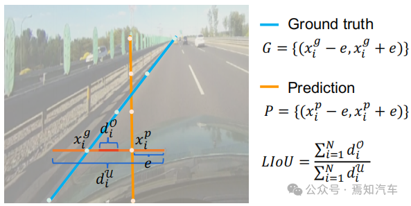
As shown in the figure below, the line intersection and union ratio IoU can be calculated by integrating the IoU of the extended segment according to the sampled xi position.

Figure 4. Line IoU diagram
#As shown in the formula shown in the figure above, from The definition of line segment intersection and union ratio IoU begins to introduce line IoU loss, which is the ratio of interaction and union between two line segments. For each point in the predicted lane as shown in Figure 4, first extend it (xpi) into a line segment with radius e. Then, the IoU between the extended line segment and its groundtruth can be calculated, written as:

where xpi - e, xpi e is xp The expansion point of i, xgi -e, xgi e is the corresponding groundtruth point. Note that d0i can be negative, which enables efficient information optimization in the case of non-overlapping line segments.
Then LIoU can be considered as a combination of infinite line points. To simplify the expression and make it easy to calculate, convert it into discrete form,

Then, the LIoU loss is defined as:

Where −1 ≤ LIoU ≤1, when two lines overlap perfectly, then LIoU = 1, when the two lines are far apart, LIoU converges to -1.
Calculating lane line correlation through Line IoU loss has two advantages: (1) It is simple and differentiable, and it is easy to implement parallel computing. (2) It predicts the lane as a whole, which helps improve the overall performance.
6. Training and inference details
First, forward sample selection is performed .
During the training process, each ground truth lane is dynamically assigned one or more predicted lanes as a positive sample. In particular, the predicted lanes are sorted according to the allocation cost, which is defined as:

Here Ccls is the focal cost between the prediction and the label. Csim is the similarity cost between the predicted lane and the real lane. It consists of three parts. Cdis represents the average pixel distance of all valid lane points, Cxy represents the distance of the starting point coordinates, and Ctheta represents the difference in theta angle. They are all normalized to [0, 1]. wcls and wsim are the weight coefficients of each defined component. Each ground truth lane is assigned a dynamic number (top-k) of predicted lanes according to Cassign.
Secondly, there is the training loss.
Training loss includes classification loss and regression loss, where regression loss is calculated only for specified samples. The overall loss function is defined as:

Lcls is the focal loss between prediction and label, Lxytl is the regression of starting point coordinates, theta angle and lane length smooth-l1 loss, LLIoU is the line IoU loss between the predicted lane and the ground truth. By adding an auxiliary segmentation loss, it is only used during training and has no inference cost.
Finally, there is effective reasoning. Filter background lanes (low score lane prior) by setting a threshold with classification score and use nms to remove high overlap lanes afterwards. This can also be nms-free if using one-to-one allocation, i.e. setting top-k = 1.
In this paper, we propose a cross-layer refinement network (CLRNet) for lane detection. CLRNet can utilize high-level features to predict lanes while leveraging local detailed features to improve localization accuracy. In order to solve the problem of insufficient visual evidence of lane existence, it is proposed to enhance lane feature representation by establishing relationships with all pixels through ROIGather. To regress lanes as a whole, a Line IoU loss tailored for lane detection is proposed, which significantly improves performance compared to the standard loss (i.e., smooth-l1 loss). The present method is evaluated on three lane detection benchmark datasets, namely CULane, LLamas, and Tusimple. The proposed method significantly outperforms other state-of-the-art methods (CULane, Tusimple and LLAMAS) on three lane detection benchmarks.
The above is the detailed content of CLRNet: A hierarchically refined network algorithm for autonomous driving lane detection. For more information, please follow other related articles on the PHP Chinese website!


