Automobile functional safety aims to control the risk of personal harm caused by the failure of electronic and electrical systems within a reasonable range. The following figure is a common electronic and electrical system hardware composition diagram. The components of an electronic and electrical system, in addition to the visible hardware in the figure, also include software that is not visible in the figure.
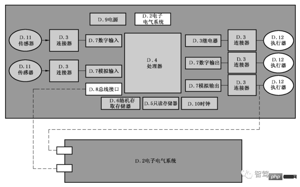
##Figure 1 Commonly used electronic and electrical hardware systems
The failure of electronic and electrical systems includes both systemic failures caused by software and hardware design errors and failures caused by random hardware failures. According to the system architecture, various safety mechanisms need to be designed to prevent and detect functional failures, and to avoid or reduce the harm when a failure occurs. This requires a strong functional safety software architecture to manage and control these safety mechanisms and reduce the overall development difficulty of functional safety.
Currently, E-GAS (Standardized E-Gas Monitoring Concept for Gasoline and Diesel Engine Control Units) is undoubtedly the most widely used security software architecture solution. Although E-GAS was originally proposed as a safety architecture solution for gasoline/diesel engine management systems, after simple adaptation, it can also be used in body systems, transmission systems, and new energy three-electric systems, etc., with very good performance Extensible and widely used.
The picture below is the three-layer software architecture design plan of E-GAS. From top to bottom, the software is divided into Level1~3, a total of three layers. Level1 is the function implementation layer (function level) , Level2 is the function monitoring level, and Level3 is the controller monitoring level. This architecture forms a good layered monitoring framework and effectively realizes functional safety decomposition. The safety decomposition strategy of QM (ASIL X) ASIL X (ASIL Functional redundant software or safety measures (Level 2, Level 3) are developed according to the highest requirement level ASIL X (ASIL X), which can effectively reduce the safety development cost of functional software.
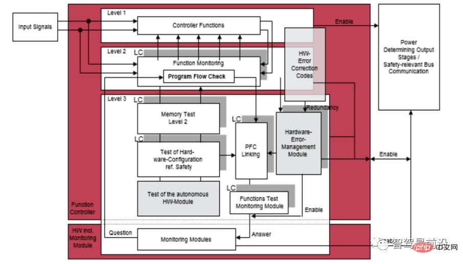
##Figure 2 E-GAS three-layer monitoring architecture solution
Level1 function implementation layer##Level1 is the function implementation layer, which completes specific function implementation, such as for motor controllers In other words, this layer converts the requested torque into the torque output of the motor.
Level2 function monitoring layer Level2 is the function monitoring layer, used to monitor Level1 Whether the function operates normally. The core of Level2 is to design a method to determine whether Level1 is running normally. Although the method of judging whether Level1 is running normally is often related to the function being monitored, different monitored functions have different judgment methods, such as through software diversification and redundancy. However, there are also some judgment methods with wider application, such as rationality check.
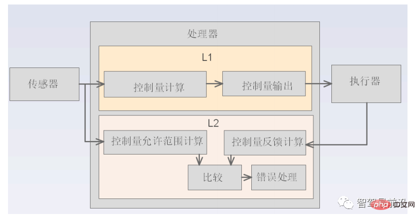
As shown in the figure above, when Level2 uses the rationality verification method to determine whether the Level1 function is operating normally, it first calculates the reasonable range of the allowed output of the control quantity based on the signal input by the sensor, then calculates the actual output quantity fed back from the actuator, and finally determines Whether the actual output volume of Level1 is within the allowed reasonable range. If it is beyond the reasonable range, it is determined that Level1 function is abnormal and error processing is performed.
Level3 controller monitoring layer
Level3 is the controller monitoring layer, mainly composed of Three parts of functional composition.
Electronic and electrical system hardware diagnosis: Monitor electronic and electrical system hardware failures, such as: controller CPU core failure, RAM failure, ROM failure, etc.
Independent monitoring: After a controller-related fault occurs, the controller can no longer reliably execute safety-related logic. In order to ensure safety, additional external independent monitoring modules are required. Ensure that even after a serious failure occurs in the MCU, it can still enter a safe state. This additional independent monitoring module is usually a power management chip with integrated watchdog.
Application flow check: Monitor whether the monitoring programs of Level1 and Level2 are running normally. This monitoring function is implemented by binding program flow inspection and watchdog feeding. If the monitoring programs related to Level1 and Level2 do not run in the set order, or are not executed within the specified time, the program flow check fails and the dog cannot be fed normally, thus entering the system safety state.
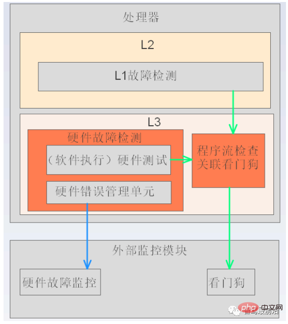
##Figure 4 Level3 functional block diagram
When it comes to functional safety and software architecture, we can look at the two dimensions of "software architecture that conforms to functional safety" and "functional safety software architecture" to look at the relationship between them.
The former focuses on the compliance of our software architecture design process with functional safety from a software development perspective, that is, our software architecture design process needs to meet the various requirements proposed by ISO 26262. Requirements, such as: marking methods, design principles, design element requirements, security analysis requirements, error detection mechanism requirements, error handling mechanisms and design verification methods, etc. Among them, the mainstream method of security analysis at the software architecture level is "software FMEA (Failure Mode and Effects Analysis)" and "Software DFA (Dependent Failure Analysis)".
The latter focuses on supporting system-level functional safety from the perspective of embedded software systems. Based on the idea of E-Gas security architecture, we believe that "layered monitoring ideas", "security measures" and "diagnostic framework" are the core of "functional safety software architecture", and "layered monitoring ideas" and "security measures" are above As stated in the article, the rest of this section mainly focuses on the "diagnostic framework". Regardless of whether the basic software development platform we use is AUTOSAR CP, AP or non-AUTOSAR, the design ideas of the functional safety software architecture are similar, and are explained here based on AUTOSAR CP.
1) Technical requirements for functional safety diagnostic framework
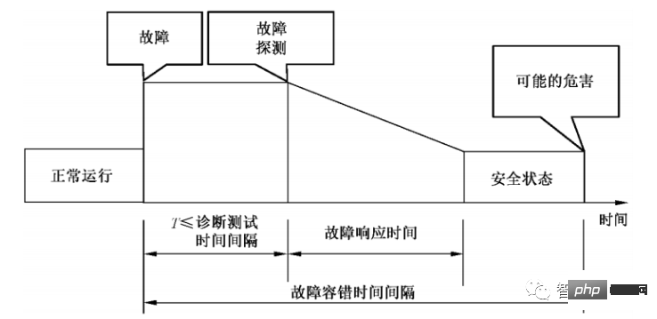
##Figure 5 Fault response time and fault tolerance time interval
We combine FTTI (fault tolerant time interval) to understand the fault diagnosis process. The period from the occurrence of a fault to the occurrence of possible hazards is the FTTI time. During this period, there are mainly diagnostic tests, fault response processes, and the hope of entering a safe state before possible hazards occur (Figure 4.1-8). The diagnostic test process needs to consider diagnostic test triggering, fault confirmation (debounce), etc.The fault response process needs to consider entering a reasonable operating mode (such as: Fail safe, Fail operational, Emergency operation, etc.), fault storage, etc.
2) Interpretation of foreign diagnostic framework technology Before interpreting the diagnostic framework technology, there are two suggestions for reference. ① Suggestion 1: Determine the timing of diagnostic testing based on requirements a. When powering on: Here is an explanation based on a typical application requirement. The safety mechanism and the corresponding functions form a double point. In order to reduce the failure rate of latent multi-point faults, the safety mechanism generally needs to perform self-checking during the system startup phase (when powered on). Additionally, diagnostic test synchronization issues need to be considered in multiprocessor systems. b. Runtime: Generally divided into periodic diagnostic tests and conditional diagnostic tests. The definition of the diagnostic cycle needs to consider the constraints of FDTI (fault detection time interval), and conditional diagnostic tests are generally diagnostics of a function when a state transition occurs or before activating a function. c. When powering off: You can choose to perform some time-consuming tests, and the test results are generally processed at the next startup. ② Recommendation 2: Carry out group diagnostic tests In order to facilitate diagnostic management (including diagnostic triggering and fault response, etc.), according to the critical fault/ Non-critical faults, diagnostic test timing and other factors are grouped. If a critical fault is detected during power-on, such as Core Fault, Ram Test Fault, etc., then the fault response can be processed in a silent state (such as: MCU is in continuous reset state).
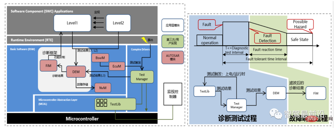
##Figure 6 "Functional Safety Diagnosis Framework" and "Functional Safety Diagnosis Control Flow"
E-Gas three-layer monitoring framework Level1 (function level) and Level2 (function monitoring level) are located in the ASW (application software, that is: SWC in Figure 4.1-9) layer, Level3 (controller monitoring level) is located at the BSW (basic software) layer. The "Diagnostic Framework" is also located at the BSW layer. As mentioned above, it mainly covers diagnostic testing and fault response processes. Its composition and working process are introduced below:
The above is the detailed content of Smart car functional safety software architecture. For more information, please follow other related articles on the PHP Chinese website!
 What is the difference between JD International self-operated and JD self-operated
 What happens when software crashes?
 modify ip
 What is the difference between rabbitmq and kafka
 The difference between paste mask and solder mask
 What are the data storage methods?
 What are the methods for detecting ASP vulnerabilities?
 How to delete blank pages in word without affecting other formats


![[Web front-end] Node.js quick start](https://img.php.cn/upload/course/000/000/067/662b5d34ba7c0227.png)